Water level Controller Using arduino


Some time when we forget to switch off the submersible pump then the upper tank water will be overflow until we get noticed. or some time in a middle of a bath the tank water get empty . and every day we need to switch  and carefully switch off the motor after the tank get filled  even we dont know how much water in the tank.

so I design this Automatic water level controller

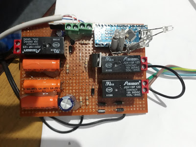
I use Arduino nano in this project and wright a program and upload in it.

Use a ultra sonic sensor for sensing water level . i fix the sensor in the lid of water tank and connect the control box with a 4 core cable.

the control board has arduino nano and color LED 's for the water level

the red led for indicating water level below 10%

amber LED indicate water above 25%

yellow is above 50%

green is above 75 %

when the water level goes below 10% the the ultra sonic sensor sense that level and arduino code check the main voltage. if it normal   decide to switch on the pump through a relay for a second this is parallel to the start button of manual pump starter switch.

when the motor is running a long beep sound  here once and a blue LED blinking.

after the water level reach above 90% the arduino  switch a relay for a second witch switch of the manual stop button. and gives a short beep

the current water level always show in the device 

and again the water reach a level lower than 10 % the motor start again automatically.

the pump can run manually also OFF  at any time .even the this water controller is on .

NB:before use this device for the first time the tank level should be calibrated once and put the value in the Program and I updated the code.

The device work very good but the  Hot water vapor formed inside the tank make the ultrasonic sensor failure. So I remove  the normal Sensor and use a water proof utrasonic sensor and the problem solved.

future plan: i want to update this project with OLD  Display for water level indication.

and also use Solid state pump control circuit instead of relays .

also use wireless to connect sensor and the device.
Comments

Popular posts from this blog

How to read value of a Capacitor ?

Capacitance is the ability to store electrons and is measured in Farads.One Farad is a very large value! So most capacitors used in electronic circuits  are measured in MicroFarads (uF) or even Picofarads (pF). Capacitance = Q / V Where Q is the charge and V is the voltage. Thus the capacitance is the charge divided by voltage. The important parameters of the capacitor are 1. Value -Value is marked on the capacitor directly or in colour codes 2. Tolerance -It indicates how much more or less the actual capacitance of the capacitor 3. Working voltage -It is the maximum voltage a capacitor can withstand before the dielectric breakdown 4. Leakage current .There is always small leakage current in all capacitors. Ideally this should be zero. But no capacitor is perfect without leakage current. Tantalum capacitor is comparatively better with minimum leakage current  Value 1pf (Pico Farad)    = 0.001nf (Nano Farad) 1nf (Nano Farad)   = 0.001μf (Micro Farad) 1μf (Micro farad) =

Ring tester

 In my Electronic repair job I found normal multimeter is somewhat limited  in certain area. so special tools are needed for saving  a lot of time  Ring tester is one of this kind .helping me to check small hi Q inductors SMPS transformer, TV Deflection coils ,LOT ,line driver transformer and almost any inductor working on hi frequency.Normal multimeter can only identify a open coil ,but not a shorted windings.  I found some commercial available ring tester. but it is not available in local shops of my area.also it seems priced high. So  I decided to make a ring tester of my own. Below is the one I successfully made from the junk box components. I found it very useful. and now it is one of my best test tool collection. Two Ic's, few LED's ,one plastic container and few resistors  made this wonderful tool. If we test it with primary of SMPS transformer or LOT windings of a good one shows all its LEDs will light. depending on the inductive reactantce  the number of LED 's

Transistor numbers and codes

Most transistor markings follow one of these codes: JEDEC, JIS or Pro-Electron. For ICs, look for known numbers (e.g. 741, 4001, 7400) between the prefix and the suffix. Don't confuse it with the date code. ICs typically have two numbers: The part number and the date code. 1. Joint Electron Device Engineering Council (JEDEC) These part numbers take the form: digit, letter, sequential number, [suffix] The letter is always 'N', and the first digit is 1 for diodes, 2 for transistors, 3 for four-leaded devices, and so forth. But 4N and 5N are reserved for opto-couplers. The sequential numbers run from 100 to 9999 and indicate the approximate time the device was first made. If present, a suffix could indicate various things. For example, a 2N2222A is an enhanced version of a 2N2222. It has higher gain, frequency, and voltage ratings. Always check the data sheet. Examples: 1N914 (diode), 2N2222, 2N2222A, 2N904 (transistors). NOTE: When a metal-can version of a JEDEC tra